|
|
|
Who's Online
There currently are 5937 guests online. |
|
Categories
|
|
Information
|
|
Featured Product
|
|
|
 |
|
|
There are currently no product reviews.
 ;
Exactly what was needed to assess the product - excellent value and great service
 ;
Nice to have the service manual for the Sony DCR-TRV345E now. The document is of excellent quality.
;
MACKIE HR824 26 pages English-only Service Manual contains:
1) HR824 technical overview with the description of front and rear panel switches.
2) HR824 specs
3) Block Diagram
4) Wiring Diagram
5) Packaging management
6) Spare part & final assembly list (for PCB rev A and B) + exploded view
7) Test Procedures (where, how to measure voltage...) including Test Point diagram on the PCB.
8) IC and Transistor charts.
Excellent guide: very clear, good scan quality enabling us to print readable diagram :-)
Note:
Mackie HR824 make extensive use of surface mount devices (SMD). Service on the HR824 must
only be undertaken by experienced service technicians with the right tools, experience and patience to perform surface mount rework when needed.
;
This Service manual is very well scanned and its clean to read, no any anti-theft words that un-english could understand. I got my CCD600 working with this manual and it´s clear shematics :)
;
I was very pleased with the service provided and was surprised at how good the quality was of the manual. I thought it may be a third generation copy or so, but it is as good as the websites that charge 3 times this much. I repair some electronics for family and friends without charge, so this is perfect for me. Thank you very much.
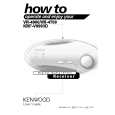
KRF-V7773D/V7773D-B/V9993D
DISASSEMBLY FOR REPAIR
HOW TO REMOVE THE FRONT PANEL AND THE MOTOR.
1. Take out the connectors (1) {X07,CN1/X13(CN7,CN8)} and the AC connetor(2). 2. Take the lead (3) out of CN301 on X11(A/4) PCB. 3. Take out the screws (4) and (5). 4. The front panel can be separated by removing 2 hooks (6) on the sub panel. 5. To separate the motor from the front panel, remove the screws (7).
MOTOR
2
AC CONNECTOR X07,CN1
1 7 x5 4 x5 4
1 1
X13
(G/8)
X25
CN8
CN7
H/P PCB
3
X11
(A/4)
CN301
6 x2 HOOK 5 x5 5
HOW TO REPLACE THE POWER TRANSISTOR.
1. The rear panel can be separated by removing screws (1) on the rear panel. 2. Take the AC connector out of CN2 on the X07(C/7). 3. To separate the chassis from bottom chassis, remove the screws (2). 4. Remove CN21 and screws (3) on X13(C/5). 5. Remove screws (4 to 7). 6. The fan motor can be separated by removing screws (8) and the connector (CN12) on X07 PCB. 7. Take the PCB X25(B/9), X11(C/4)} out of X07. 8. To separate the main PCB (X07) from the bottom chassis, remove screws (0). 9. Set up the PCB as figure (-). 10. Replace the defective transistors.
2 9 7 5
(C/9)
X25
X05-5130-11
4 7 x2 7 6 6
(C/5)
X13
CN21
3 x2 3 x2 8 x9
2
X07 CN12
2 2 2
2
2
X07-3150-10
(A/5)
11 10 10
CN2
10 10
10
CN14 CN6 X25
(B/9)
X07
(C/7)
X11
(C/4)
10 x3
4
1 x70
|
|
|
> |
|